Multi-scale Synchroton X-ray Imaging Quantifies Li-ion Battery Failure
Researchers from the Beijing Synchroton Radiation Facility, the European Synchroton Radiation Facility, the SLAC National Accelerator Laboratory, Virginia Tech and Purdue University have developed the most comprehensive view yet of how repeated charging damages lithium-ion battery electrodes. The research, which was recently published in Advanced Energy Materials (Adv.?Energy?Mater. 2019, 1900674), could potentially help manufacturers design more reliable, longer-lasting batteries for smartphones and cars, as well as advance basic scientific research concerning the failure of battery materials.
The goal of the research was to understand and quantitatively define what leads to the failure of lithium-ion batteries. Previous studies had either focused on individual areas or particles in the cathode during failure or looked at cell-level behavior without offering sufficient microscopic detail. In contrast, this study relied heavily on synchrotron multi-scale X-ray imaging technology to provide the first global view of battery failure offering an unprecedented amount of microscopic structural details to complement existing studies in the battery literature.
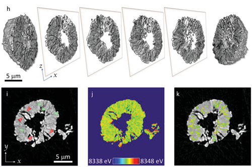
Fig. 1. Structural defects in NMC622 at nano and meso scales. Panel (h) shows the 3D rendering of the particle morphology with a few xz slices through different positions displayed in the center. Panel (i) is an xy slice through the center of the particle. Two different types of cracks, i.e., wide-open cracks (black; red arrows in (i)) and fine cracks (gray pattern with lower contrast; green arrows in (i)), can be observed. Panel (j) is the false-colored map (colormap shown in the inset) of local Ni K-edge energy for the same xy slice in (i). The local edge energy over the fine cracks was segmented and displayed in panel (k). The scale bar in (a) is 10 nm; for both (h) and (i) it is 5 μm.
The research team first employed nano-resolution X-ray spectromicroscopy to visualize the micro-cracks and corresponding chemical responses in a single charged NMC622 particle after it was cycled extensively (50 cycles at a rate of 5C). As shown in the three-dimensional (3D) rendering of the particle morphology in Fig. 1h-ik, two types of micro-cracks coexist in the imaged NMC622 particle: well-developed cracks (black; see red arrows) and newly developed cracks (black; see red arrows). The surface of the particle and the well-developed cracks appear to be more oxidized in Fig. 1j as indicated by the red contour. The well-developed cracks facilitate the infiltration of the liquid electrolyte, thus activating lithium-ion deintercalation at the crack surface. In contrast, the change in the spectroscopic fingerprint for the newly developed cracks is less obvious. As shown in Fig. 1k, the newly developed cracks are scattered throughout the particle. No obvious contrast (in terms of the Ni oxidation state) appears between the bulk and the cracks in this early stage of development. This is likely due to the lack of liquid electrolyte wetting at these regions.
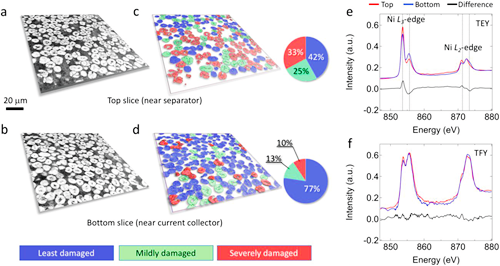
Fig. 2. Comparison of the top and bottom layers in an NMC622 electrode that has gone through 10 fast cycles at a rate of 5C. Panels (a) and (c) (color-coded) are the same lateral slice of the particle layer that is close to the 10-cycle electrode’s top surface (near the separator). Panels (b) and (d) (color-coded) are the same lateral slices for the first layer of particles close to the aluminum current collector (bottom of the 10-cycle electrode). The relative particle cracking probabilities for these two slices are quantified in the corresponding pie charts. Panels (e) and (f) are the surface-sensitive soft XAS results for the top (red) and the bottom (blue) of the 10-cycle electrode in total electron yield (TEY) and total fluorescent yield (TFY) modes, respectively.
In order to study the influence of the development and variation of internal cracks in battery cells on the performance of lithium batteries, the researchers used X-ray phase contrast imaging technology to scan thousands of particles in a lithium-ion battery electrode at once. Such unprecedented morphological detail facilitated very detailed quantification. For example, Fig. 2a-2d show two lateral virtual slices (xy plane) at different z positions. The difference shown in Fig. 2e indicates that the top of the electrode experienced more severe undesired local phase transition from the layered structure to a mixture of spinel and rocksalt structure. In contrast, the bulk sensitive total fluorescence yield (TFY) signal shows very little difference between the top and bottom of the electrode. In other words, at the electrode level, the researchers didn’t observe significant state-of-charge (SOC) heterogeneity between the top and bottom of the electrode after long-term relaxation. While mesoscale SOC heterogeneity (within individual particles) might persist after long-term relaxation, it does not seem to be the case at the electrode level since charge transfer among active particles is facilitated by the interconnected liquid electrolyte and conductive carbon networks.
This study offer a diagnostic method for understanding how the performance of lithium battery cathode materials degrades. In turn, it can help people establish the interrelationship between the macroscopic properties of battery materials and their microscopic material structure. The multiscale imaging technology used in this research will play an even more important role as this technology continues to advance.
Contact Information
Mr. Guo Lijun
ljguo@ihep.ac.cn
Related News

Second Run of 2017 Concluded at BSRF
12-01,17
This year's second dedicated run at the Beijing Synchrotron Radiation Facility (BSRF) was open to...
First Amber Dinosaur Specimen Found at Beijing Synchrotron Radiation Facility
12-16,16
A group of scientists from the Institute of High Energy Physics (IHEP), in collaboration with pal...